|
|
|
A Control Interface for the K3 |
|
In November 2008 I jumped on the bandwagon and purchased a K3 (#02131)
-- primarily to replace the IC-7000 that I had been using for
contesting from my home station.
However, use in only a
few contests revealed the K3 to be a great radio. That was no
surprise given all of the reviews and endorsements of the
radio by
top-notch DXers and contesters. So I decided I needed to make use of it
to provide better ears in my mobile contesting activities. Although the
K3 is relatively small and lightweight it's still a bit large for use
from the front passenger seat which is where I like to do mobile
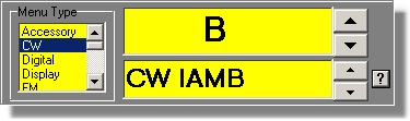
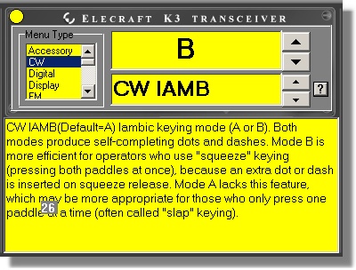
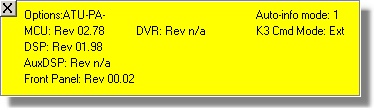
contesting, and it doesn't come with a remote control head. The challenge was obvious: develop a module for the K3 that would integrate with CQ/X and would allow placement of the radio in the rear of the vehicle with full controllability from the operating position in the front. Review of the K3 programmer documentation revealed an extensive and well-documented list of functions that would, with a little programming, make the venture possible. I thought about what kind of user interface to devleop to make control from the "remote head" intuitive and easy to learn and the interface below quickly became the obvious choice. 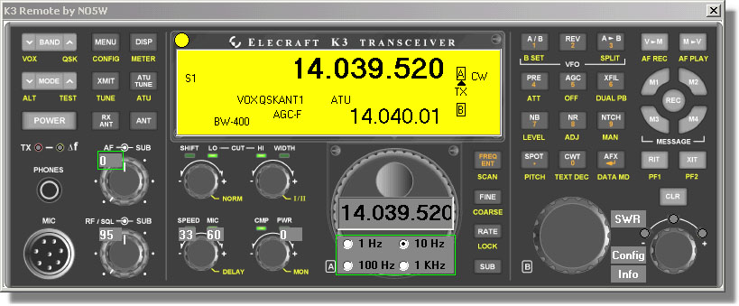 The basic platform for the user interface is a high resolution image scanned from the front of the K3 User Manual. For the most part the interface works in exactly the same way as the real front panel of the radio, the main exceptions being cases where there is more/less capability on the PC vs the capability of the actual K3 hardware. You can also see that some items (Config, Info, and various data entry/readout items) have been added. Here are some of the features: Button Controls: Each of the buttons performs the indicated function and the Tap/Hold feature is implemented with configurable hold time. In addition, the left/right mouse buttons can be used respectively for Tap/Hold. Frequency Entry: Clicking on the Freq Ent button opens an edit window on the VFOA part of the "LCD" display from which a frequency can be typed in.  Frequency Tuning: Frequency tuning is currently performed with the cursor and page up/down keys. The tuning increment for the cursor keys is set using the radio buttons shown on the main tuning knob. The tuning increment for the page keys, which is intended for larger frequency changes including band changes, is set on the config page described below. I've obtained a Shuttle Pro 2 and will be experimenting with it as a tuning device and as a means of setting the rotary controls. Rotary Controls: Rotary controls including AF Gain, Sub AF Gain, RF Gain, Sub RF Gain, Speed, PWR, etc are controlled using the cursor keys with the value read out in the small window shown on the control. Since some of these controls are more frequently used than others it may be desirable to access them using the Tab key rather than moving the mouse. Controls to include as tab stops and the tab order are specified in the Config dialog below. LCD Display: This display shows essentially the same information, including transitory status info, as on the radio with the following current exceptions: S-meter readout is in text form, Bandwidth information is also in text form. There is a separate "LCD panel" for a graphical S-meter that is accessed using the small yellow circle near the LCD display. There are actually several layers of the LCD display including the following:
The
following LCD layer
which shows installed options and firmware revisions, is accessed by
clicking on the Info button.
 Clicking
on the Power
button will power
down the radio but to make sure that this is the desired action the
following "do you really want to do this" LCD layer is presented.
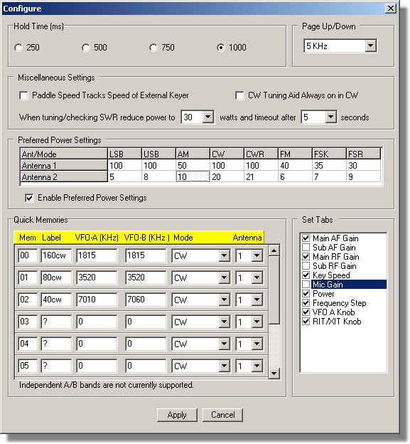
 Configuration
Button/Dialog:
A small Config button, placed near the RIT/XIT area is used
to access
the Config Dialog below for setting parameters
associated
with the remote kit including: Hold time for discriminating
between Tap and Hold presses of the buttons, Frequency increment for
the page keys, Tab stops and Tab Order for the rotary controls,
quick-memory parameters, and preferred power levels based on antenna
selection and mode.
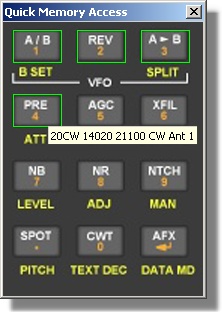
 Quick
Memory Dialog:
After the Quick Memories have been configured using the above dialog,
clicking on the M->V button calls up the following dialog for
choosing the memory. As shown in the screen shot
below those
quick memories that have been configured are highlighted. Hovering over
each of them gives information on the associated quick memory. Clicking
on the desired quick memory writes that information into the radio.
 SWR
Button:
The small SWR button, near the RIT/XIT area, is used
to check
the SWR at the antenna. Clicking on this button will put the antenna
tuner into bypass mode, reduce power to a specified level, activate the
tune button for a specified number of seconds, display the SWR on the
button face, and then deactivate the tune button returning the power
level and antenna tuner to their previous states. The power level and
number of seconds associated with the SWR check are set in the
Configuration Dialog above.
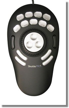
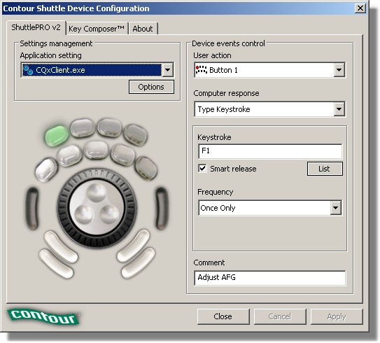
A Control Subset for the K3The full interface described above allows almost complete control and monitoring of the K3 but takes up a lot of screen real estate, especially when operating mobile on a laptop with its small screen, so beginning with Patch 177-05 the dialog below is provided as an alternate means of controlling and monitoring often used K3 parameters.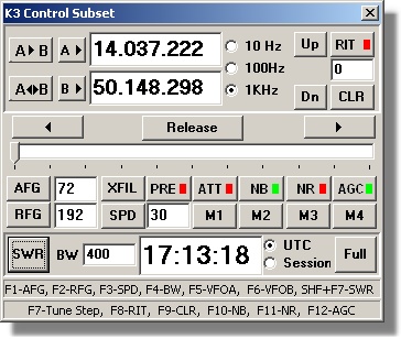 SWR button: Click on this button to measure the SWR of the antenna at the current VFO-A frequency with the K3 antenna tuner removed from the path. The SWR will be displayed in the window normally reserved for the clock and when tuning is complete the clock window will revert to showing the selected time. Clock buttons: Use these radio buttons to select whether to show normal (UTC) time or the time remaining in the contest session. In order for the session time to be correct it must be set up in the main user interface using either the wizard or the menu item Display | Set Session Clock. Entry-less controls: Controls labeled PRE, ATT, NB, NR, AGC, M1, M2, M3, M4, Up, Dn, A<->B, A->B and CLR do not require entry of a value and are straightforward since they perform the same actions as on the full interface. Up(Dn) moves the band up(down) and A<->B exchanges VFOs A and B. For the on/off controls red indicates OFF and green indicates ON. For AGC there are three states: OFF (red), Slow (yellow), and Fast (green) and the button sequences between those states. Entry controls: The remaining controls A->, B->, RIT, AFG, RFG, XFIL, and SPD (speed) require entry of a numerical value. To save space a single shared slider is provided for inputting the values for each of these. Each control in this set consists of a button for assigning the slider to the control and an edit window in which to display the value of the controlled quantity. The cursor left and right keys can be used with the slider to make small incremental changes if it is not desired to use the mouse. Page up and down keys may be used with the slider to make larger incremental changes. Each control has page and cursor key increments appropriate to the quantity being adjusted. A Remote Tuning Knob for the K3Using the above K3 Control Subset dialog and its associated function keys along with a Shuttle Pro 2 device enables the user to implement a multi-function remote tuning knob for the K3. As shown in the image below the Shuttle Pro contains fifteen buttons, a wheel, and a shuttle each of which can be configured to perform a function in the focused window using the configuration dialog shown.
Next Steps An intriging idea is to implement the above interface in a small (e.g. 7-8 inch) touch screen such as the ones made by Lilliput and Xenarc for use in automotive applications. If that works out you would have a full featured "K3 remote kit" a little smaller than the actual front panel. I haven't yet bit the bullet and bought one of these devices for testing the concept but if there are those that have access to one of these screens and would like to prove the concept please contact me at the address on the support page. In its current form use of the above interface in a logging program other than CQ/X would require some programming to interface to the DLL. However, I plan to create a version that is more easily interfaced using virtual serial port technology. It also would be interesting to network-enable the interface for true remote control across the internet. Testing/Evaluating the K3 Module If you are interested in testing the K3 module you will need at least version 1.7.5 with all six patches applied or version 1.7.6 patched through Patch 176-03 but it would be best to download the latest version and it's associated patches in order to get all features including capability to use the Shuttle Pro. If you are not already a user of CQ/X you should also download the Quick Start Guide for Testing the K3. Copyright: C.W. Sanders, NO5W Last Updated: 09-March-2013 |